Resources
A Comprehensive Guide to Design a Light Electric Vehicles (LEV) Traction Inverter for a Sustainable Future

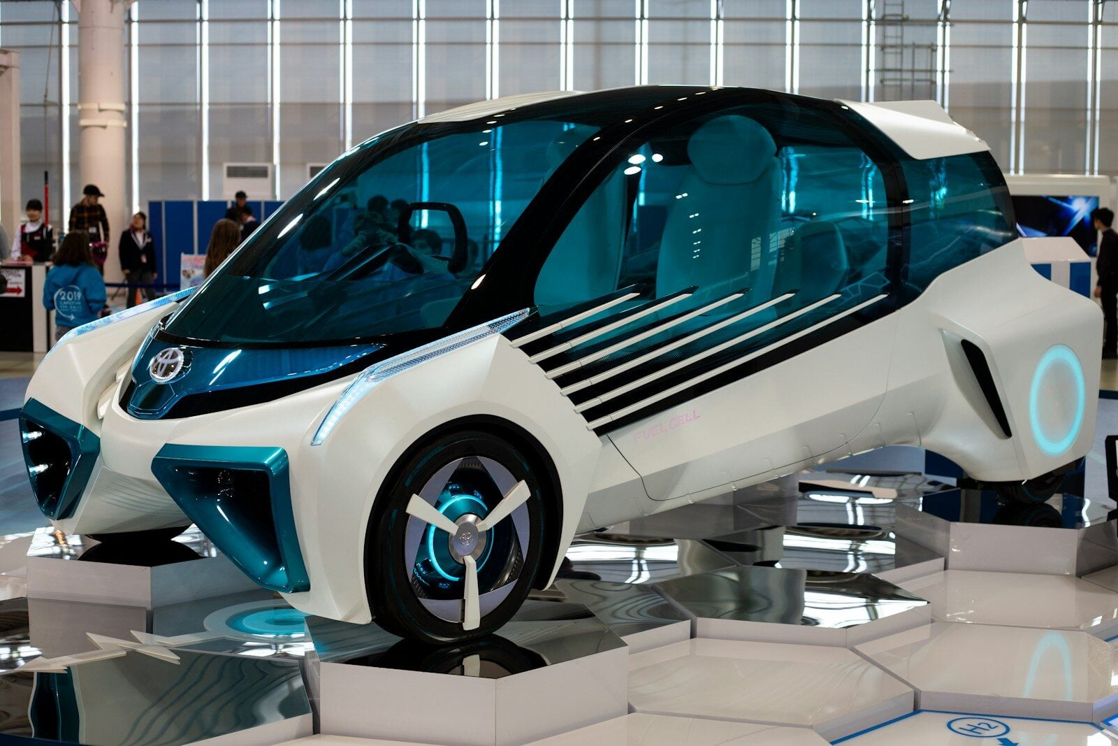
Light Electric Vehicles are revolutionizing the mobility market by providing low cost, energy efficient electric vehicles. The current LEV market growth is driven by advancements in power electronics technology due to strong collaboration between the OEMs and semiconductor manufacturers.
LEV comprises of an advanced traction system that is driven by low-voltage inverters, for efficient and intelligent motor control. The LEV traction inverter converts the direct current (DC) from the power source to alternating current (AC) to drive electric motors. In this blog, we will explore the building blocks of a typical LEV traction inverter.
LEV Traction Inverter System Architecture
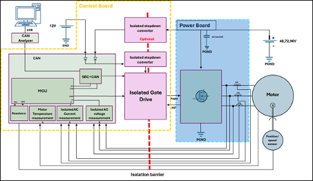
A well-designed traction system is essential for electric vehicles to run properly and efficiently. The LEV traction inverter system comprises of a control board, power board and supply, sensor, interactive display, safety mechanism and motor control. In this system, the traction inverter design controls motor speed and torque, so high energy efficiency is critical because it extends driving range. A typical electric vehicle traction system should work within a voltage range of 24V to 96V, including 48V, 72V, and 96V applications, and be able to deliver up to 5 kW of power at a switching frequency of 10 kHz.
LEV Traction Control Board
The control board is the brain of the system and should comprise of automotive grade (AEC-Q100 and ASIL-B) microcontroller and system base chip. A high-compute low power automotive-grade microcontroller with multiple communication interfaces is required for inter-vehicle communication whereas the system base should comprise of power management components such as buck converters, linear regulators and gate drivers for safety and voltage regulation capabilities.
Sensors
Sensors measure key parameters such as voltage, current, temperature, and position, and the inverter monitors current, voltage, and temperature to optimize motor performance while providing feedback to the control mechanism for efficient motor control and system safety. While designing the system, sensor selection should be done by taking into consideration harsh conditions and automotive standards. To ensure thermal stability, precise speed and position sensing, there should be minimum delay in data relaying. The block should also incorporate components for blocking electromagnetic interference to make it suitable for automotive environments.
Communication Interfaces
Seamless and secured interaction is important for efficient diagnostics, control, and data exchange across the vehicle network. The inverter system should integrate modern interfaces including CAN FD, LIN to provide a cost-effective solution for subsystem communication at different data rates.
Safety Mechanism
Safety is an imperative aspect to be considered while designing an LEV traction inverter. A scalable design with integrated safety should also support functional safety and compliance goals, including IEC61508 pre-compliance. The system should be designed to incorporate safety mechanisms against operational faults like component failures short circuits, over currents and overheating, to ensure stable operation. DC link capacitors for excess current discharge, gate drivers for isolation between power and control circuits, shunt resistors to avoid over currents are some of the common approaches that ensure the operational safety under demanding conditions.
Power Supply and Module
A typical inverter should support two supply configurations including dual and single supply to cater different needs of the vehicles. In the dual supply power mode, the control and power sections are powered by different sources based on the voltage needs whereas in single-supply setup, converters are included for voltage conversion.
The power module handles high-voltage/high-current block that translates battery DC power into multi-phase AC power to drive the motor. In this inverter design, high-speed semiconductor switches are used to produce three-phase AC output. It should handle power levels upto 20 KW and typically operates between 24V and 96V.
A typical power module comprises of:
- Insulated-Gate Bipolar Transistor (IGBT) that helps converting the DC link voltage to AC by rapidly turning ON-OFF based on the PWM signal received from the microcontroller, with Pulse Width Modulation shaping the AC waveform.
- Amplifying driver chips to convert low-voltage PWM signals (PWM) from microcontroller to heavy-load power switches (IGBT) to control their switching speeds.
- Large film capacitors to absorb high-frequency ripple currents, voltage spikes and ensure safety.
- Sensors that provide real-time current and voltage data back to the controller module for precise field-oriented control.
Many reference designs are optimized for regenerative braking, which improves overall efficiency by converting motor-generated energy back to DC.
Motor
Permanent Magnet Synchronous Motors (PMSM) and Brushless DC (BLDC) motors are commonly used for LEV traction inverters. PMSM uses embedded permanent magnets and is ideal for mid to high-end LEVs. BDLC has trapezoidal back-EMF design with permanent magnets and is ideal for low to moderate LEVs. These motors are supplied with AC current that is controlled using Field-Oriented Control, which is used for efficient torque production and smooth delivery while providing improved efficiency and precise speed regulation.
Interactive Display
The system should include a display and interactive user interface to display, monitor and control real-time parameters. The user should be able configure the inverter parameters and initiate safety functions in case of fault detection.
Field-Oriented Control (FOC)
The primary purpose of Field-Oriented Control (FOC) in a LEV inverter is to enable efficient, and smooth motor operation by adjusting the motor’s torque and speed. This is achieved by controlling the current flowing through the motor based on the feedback / signals received from the microcontroller.
FOC integration and control depends heavily on the following hardware components:
- Microcontroller: Executes real-time FOC algorithms and control loops
- Gate Drivers: Convert PWM signals into high-power switching signals
- Current and Voltage Sensors: Provide feedback for accurate control
- Speed/Position Sensors: Enable rotor angle detection for transformations
- Communication Interfaces (CAN/LIN): Allow tuning, diagnostics, and monitoring
The combination of these components creates a closed-loop system that continuously adjusts motor behaviour in real time.
Conclusion
The traction inverter system is a critical component of LEVs, ensuring enhanced performance and higher driving range. Developed by eInfochips, it is an ideal cost-effective solution that addresses the evolving needs of the modern electrical mobility market. Featuring advanced hardware, efficient power electronics, and intelligent control strategies, the system delivers efficient and reliable operation with up to 5 kW power capacity. eInfochips’ traction inverter solution is well-positioned to support the growing demand for sustainable, high-performance, and energy-efficient transportation solutions.
For more information please refer – https://www.einfochips.com/resources/brochure/scalable-traction-inverter-reference-design-for-lev/
Frequently Asked Questions
- What is an LEV Traction Inverter?
The LEV traction inverter converts the direct current (DC) from the power source to alternating current (AC) to drive electric motors. In this blog, we will explore the building blocks of a typical LEV traction inverter, which is typically compact and lightweight for small light electric vehicles. It can also support functional safety and IEC61508 pre-compliance to help reduce design risk and address key technical challenges for lev manufacturers.
- What is a typical voltage range of a LEV Traction Inverter?
A typical electric vehicle traction system should work within a voltage range of 24V to 96V and be able to deliver up to 5 kW of power at a switching frequency of 10 kHz. Scalable power ratings in modular architectures can span 3kW to 15kW, which helps reduce design risk across different LEV classes.
- What are the main components of a LEV Traction Inverter?
The LEV traction inverter system comprises of a control board, power board and supply, sensor, interactive display, safety mechanism and motor control. Many reference designs use a tailored, modular approach to support compliance and adaptation to various vehicle classes.
Author’s Bio:

Aarohi Desai – Solution Architect Manager
Aarohi Desai is a Solution Manager for Platform Partnerships and Vertical Marketing at eInfochips, an Arrow Company. For over 16 years, she has been responsible for launching modules and development kits based on the latest platforms to accelerate development of innovative product across industry verticals.
Aarohi has a master’s degree in electrical and computer engineering from Georgia Tech, Atlanta. Prior to joining eInfochips, she was working at a leading platform company in Santa Clara as a systems engineer.


-

 Resources5 years ago
Why Companies Must Adopt Digital Documents
-

 Resources4 years ago
A Guide to Pickleball: The Latest, Greatest Sport You Might Not Know, But Should!
-

 Resources1 year ago
50 Best AI Free Tools in 2025 (Tried & Tested)
-

 Resources1 year ago
Get Paid $5000+ a month to write : Discover 30 Spectacular Websites That Reward Your Writing Effort